Products Details
Product Description D-type horizontal multi-stage pump is a single-suction multi-stage segmented centrifugal pump, which is used to transport clean water or other liquids with physical and chemical properties similar to water. The temperature of the liquid should not exceed 80 °C. It has the characteristics of high efficiency, wide performance range, safe and stable operation, low noise, long life, convenient installation and maintenance, etc. It can also be used to transport hot water, oil, corrosive or abrasive media by changing the material of the pump flow parts, the sealing form and increasing the cooling system. The product implements the standard of JB/T1051-93 "Type and Basic Parameters of Multistage Clean Water Centrifugal Pump". D-type horizontal multistage pump is mainly used for industrial and urban water supply and drainage, high-rise building pressurized water supply, garden sprinkler irrigation, fire pressurization, long-distance water supply, heating, bathroom and other cold and warm water circulation pressurization and equipment matching, especially suitable for small Boiler feed water. (Our company) All multi-stage centrifugal pumps are designed and optimized by computer. The company has strong technical force, rich production experience and perfect testing methods, so as to ensure stable and reliable product quality. Product Parameters ■ Technical parameters and model significance of D-type horizontal multistage centrifugal pump: Flow: 3.7-1350m³/h; Head: 49-1800m; Power: 3-1120KW; Rotation speed: 1450-2950r/min; Diameter: φ50-φ200; Temperature range: ≤105℃; Working pressure: ≤3.0Mpa. Model meaning: 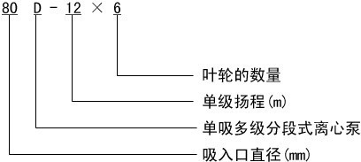 ■ Structure diagram and description of D-type horizontal multistage centrifugal pump:
 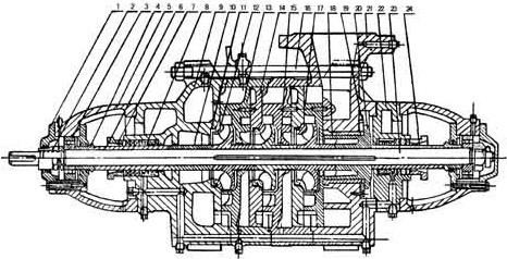 1 bearing cap, 2 nut, 3 bearing, 4 water retaining jacket, 5 shaft sleeve frame, 6 shaft sleeve armor; 7 packing gland, 8 packing ring, 9 water inlet section, 10 intermediate sleeve, 11 sealing ring, 12 impeller; 13 middle section, 14 guide vane baffle, 15 guide wing cover, 16 tension bolt, 17 water outlet section guide wing, 18 balance sleeve; 19 balance disc, 20 balance ring, 21 water outlet, 22 tail cover, 23 shaft, 24 shaft sleeve B; Features: 1. Advanced hydraulic model, high efficiency and wide performance range. 2. The pump runs smoothly and has low noise. 3. The shaft seal adopts soft packing seal or mechanical seal, the seal is safe and reliable, the structure is simple, and the maintenance is convenient and quick. 4. The shaft is a fully sealed structure, which ensures no contact with the medium, no rust, and long service life. Structure Description: The D-type horizontal multi-stage pump is a multi-stage segmented type. Its suction port is located on the water inlet section, in a horizontal direction, and the discharge port is vertically upward on the water section. Whether the water pump is well assembled or not has a great influence on the performance, especially the outlet of each impeller and the in and out center of the guide vane. A slight deviation will reduce the flow of the pump and the efficiency of the reduction of the head. Therefore, be sure to pay attention to the maintenance and assembly. The main parts of the D-type horizontal multistage pump are: water inlet section, middle section, water outlet section, impeller, guide wing baffle, water outlet section guide wing, shaft, sealing ring, balance ring, shaft sleeve, tail cover and bearing body. The water inlet section, middle section, guide vane baffle, water outlet section guide wing, water outlet section and tail cover are all made of cast iron, which together form the working chamber of the pump. The D-type horizontal centrifugal pump impeller is made of high-quality cast iron, with blades inside, and the liquid enters from one side in the axial direction. Since the pressure of the impeller is not equal to the front and rear, there must be an axial force. This axial force is borne by the balance plate, and the impeller Manufactured through static balance test. The shaft is made of high-quality carbon steel, with an impeller installed in the middle, which is fixed on the shaft with a key, a bushing and a bushing nut. One end of the shaft is equipped with a coupling part, which is directly connected to the motor. D-type horizontal centrifugal pump sealing ring is made of cast iron to prevent the high-pressure water of the pump from leaking back to the water inlet part. It is fixed on the water inlet section and the middle section respectively. The balance ring is made of cast iron and fixed on the water outlet. It forms a balance device together with the balance. The balance disc of D-type horizontal centrifugal water pump is made of wear-resistant cast iron, which is installed on the shaft and is located between the water outlet section and the tail cover to balance the axial force. The shaft sleeve is made of cast iron and is located in the packing chamber. It is used to fix the impeller and protect the pump shaft. It is a wearing part and can be replaced with spare parts after wear. The bearing is a single row radial ball bearing lubricated with calcium-based grease. The packing acts as a seal to prevent air from entering and a large amount of liquid leaking out. The packing seal is composed of the water inlet section and the packing chamber on the tail cover, the packing gland, the packing ring and the packing, etc. A small amount of high-pressure water flows into the packing chamber to act as a water seal. The tightness of the packing must be appropriate, neither too tight nor too loose, as long as the liquid can seep drop by drop. If the packing is too tight, the bushing is easy to heat up and consume power. Packing that is too loose will reduce pump efficiency due to fluid loss.
 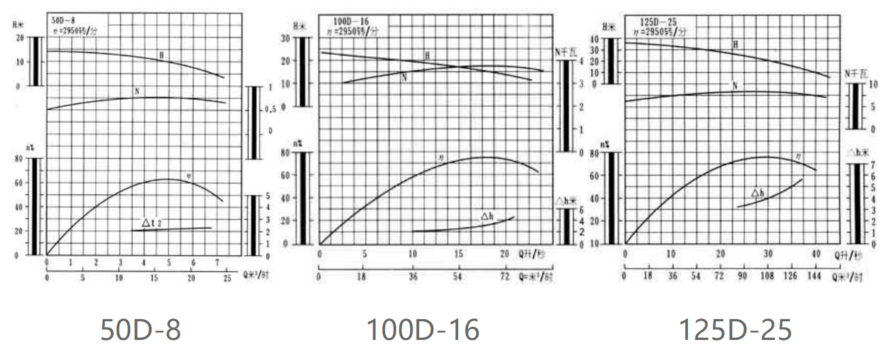 D-type horizontal multistage centrifugal pump performance curve and performance parameters:
 | D/DG/DF/MD(P)6-25 | D/DG/DF/MD(P)6-50 | D/DG/DF/MD(P)6-80 | D/DG/DF/MD(P)12-25 |
| D/DG/DF/MD(P)12-50 | D/DG/DF/MD(P)12-80 | D/DG/DF/MD(P)25-30 | D/DG/DF/MD(P)25-50 |
| D/DG/DF/MD(P)25-80 | D/DG/DF/MD(P)46-30 | D/DG/DF/MD(P)46-50 | D/DG/DF/MD(P)46-80 |
| D/DG/DF/MD(P)85-45 | D/DG/DF/MD(P)85-67 | D/DG/DF/MD(P)85-80 | D/DG/DF/MD(P)85-100 |
| D/DG/DF/MD(P)120-50 | D/DG/DF/MD(P)120-100 | D/DG/DF/MD(P)150-30 | D/DG/DF/MD(P)150-50 |
| D/DG/DF/MD(P)150-80 | D/DG/DF/MD(P)150-100 | D/DG/DF/MD(P)155-30 | D/DG/DF/MD(P)155-67 |
| D/DG/DF/MD(P)200-50 | D/DG/DF/MD(P)200-100 | D/DG/DF/MD(P)200-150 | D/DG/DF/MD(P)210-70 |
| D/DG/DF/MD(P)280-43 | D/DG/DF/MD(P)280-65 | D/DG/DF/MD(P)280-95 | D/DG/DF/MD(P)280-100 |
| D/DG/DF/MD(P)300-45 | D/DG/DF/MD(P)360-40 | D/DG/DF/MD(P)360-60 | D/DG/DF/MD(P)360-95 |
| D/DG/DF/MD(P)450-60 | D/DG/DF/MD(P)450-95 | D/DG/DF/MD(P)500-57 | D/DG/DF/MD(P)550-50 |
| D/DG/DF/MD(P)580-60 | D/DG/DF/MD(P)640-80 | D/DG/DF/MD(P)720-60 | D/DG/DF/MD(P)1100-85 |
■ Pump loading and unloading, starting, running and stopping: 1. Connection sequence: 1) Tightly install the sealing ring on the water inlet section and the guide vane baffle respectively. 2) Put the guide wings on the middle section, and then install the guide wing baffles on all the middle sections. 3) Pass the installed bushing armor and the suspected shaft through the water inlet section, and push the impeller into it, put a layer of paper pad on the middle section, install the middle section, and then push in the second impeller, and repeat the above steps. , assemble all the impellers and the middle section. 4) Install the gimbal ring, gimbal sleeve and guide vane in the water outlet section respectively on the water outlet section. 5) Install the water outlet section on the middle section, and then fasten the water inlet section, the middle section and the water outlet section together with tension bolts. 6) Install the flat punching plate and the shaft sleeve B (the 50DB pump does not have this part). 7) Install the paper pad on the tail cover, install the tail cover on the water outlet section, and install the packing, packing ring, and packing gland into the filling chamber of the water inlet section and the tail cover in sequence. 8) Install the bearing body on the water inlet section and the tail cover respectively, and fasten them with bolts. 9) Install the bearing locating sleeve, ?L ball bearing, and fix it with a nut. 10) Put an appropriate amount of butter in the bearing body, put the paper pad on the bearing cover, and install the bearing cover on the bearing body and fasten it with screws. 11) Install the coupling parts, bleed the cock and all square plugs. The disassembly is carried out according to the above steps not in reverse. (2) Installation: 1. Preparations before installation. 1) Check the water pump and motor. 2) Prepare tools and lifting equipment. 3) Check the foundation of the machine. 2. Installation sequence: 1) The whole set of water pump is transported to the site, and the motor with the base has been installed. It is not necessary to remove the pump and motor when leveling the base. 2) Place the base on the foundation, place a wedge-shaped pad near the anchor screw, and raise the base by about 20-40 mm, ready to be leveled and then filled with water screw. 3) Check the levelness of the base with a spirit level. After leveling, tighten the anchor nut and fill the base with grout. 4) After 3-4 days of cement drying, check the levelness again. 5) Wash and remove the dirt on the support plane of the base, the water pump feet and the plane of the motor feet;, and put the water pump and motor on the base. 6) Adjust the level of the pump shaft. After leveling, tighten the nut properly to prevent movement. After the adjustment is completed, install the motor. There is a certain gap between the pump and the coupling. 7) Put the flat ruler on the coupling, and check whether the axis line of the pump and the motor are coincident. Flatten the ruler, then take out a few thin iron pieces of the pad, replace the iron pieces with a planed whole iron plate, and re-check the installation. In order to check the installation accuracy, use a feeler gauge at several opposite positions to measure the clearance between the two coupling planes. The difference between the maximum and minimum clearances on the coupling plane should not exceed 0.3 mm. The difference must not exceed 0.1 mm. 3. Start and stop: 1) Clean the oil from the shaft and other oiled parts. 2) Clean the bearing and oil chamber with gasoline and wipe with cotton yarn. 3) Add calcium-based spring oil to the bearing body. 4) The test is successful. Check whether the rotation of the motor is correct. Strictly prevent the pump from turning and loosen the nut. Then start the motor. 5) Fill the pump with water or empty the pump to lead water. 6) Close the valve on the discharge pipe and the pressure gauge cock. 7) After the above process is completed, start the motor and open the pressure gauge cock 8) When the water pump is running at normal speed, the pressure gauge shows the proper pressure. Then open the vacuum gauge rotary base and gradually open the gate valve on the drain line until the required pressure is reached. 9) When stopping the water pump. Slowly close the gate valve on the drain line. Close the vacuum gauge cock. Stop the motor. Then close the pressure gauge cock. 10) When the water pump is stopped for a long time, the water pump should be disassembled. Wipe the water of the pump parts away. Apply anti-rust oil on the sliding surface and store it properly. 4. Operation: 1) Pay attention to the temperature of the water pump bearing. It should not exceed the external temperature of 351 and its limit temperature should not be greater than 751^ 2) The normal level of water leakage in the burial chamber is no more than 15 ml per minute. The compression degree of the packing gland should be adjusted at any time. 3) Regularly check the shaft device and pay attention to the temperature rise of the motor bearing. 4) During operation, if there is a rumble or abnormal sound, stop immediately to check the cause.
water transfer pump,
- ZJQ pump,
Ah Slurry Pump,
Floor Pressure Pump,
Water Pressure Pump,
Centrifugal Vacuum Pump,
High Head Slurry Pump,
Mud Pump 10 Hp,
12v Pressure Pump,
Sand Pump,
 ■ Structure diagram and description of D-type horizontal multistage centrifugal pump:
  1 bearing cap, 2 nut, 3 bearing, 4 water retaining jacket, 5 shaft sleeve frame, 6 shaft sleeve armor; 7 packing gland, 8 packing ring, 9 water inlet section, 10 intermediate sleeve, 11 sealing ring, 12 impeller; 13 middle section, 14 guide vane baffle, 15 guide wing cover, 16 tension bolt, 17 water outlet section guide wing, 18 balance sleeve; 19 balance disc, 20 balance ring, 21 water outlet, 22 tail cover, 23 shaft, 24 shaft sleeve B; Features: 1. Advanced hydraulic model, high efficiency and wide performance range. 2. The pump runs smoothly and has low noise. 3. The shaft seal adopts soft packing seal or mechanical seal, the seal is safe and reliable, the structure is simple, and the maintenance is convenient and quick. 4. The shaft is a fully sealed structure, which ensures no contact with the medium, no rust, and long service life. Structure Description: The D-type horizontal multi-stage pump is a multi-stage segmented type. Its suction port is located on the water inlet section, in a horizontal direction, and the discharge port is vertically upward on the water section. Whether the water pump is well assembled or not has a great influence on the performance, especially the outlet of each impeller and the in and out center of the guide vane. A slight deviation will reduce the flow of the pump and the efficiency of the reduction of the head. Therefore, be sure to pay attention to the maintenance and assembly. The main parts of the D-type horizontal multistage pump are: water inlet section, middle section, water outlet section, impeller, guide wing baffle, water outlet section guide wing, shaft, sealing ring, balance ring, shaft sleeve, tail cover and bearing body. The water inlet section, middle section, guide vane baffle, water outlet section guide wing, water outlet section and tail cover are all made of cast iron, which together form the working chamber of the pump. The D-type horizontal centrifugal pump impeller is made of high-quality cast iron, with blades inside, and the liquid enters from one side in the axial direction. Since the pressure of the impeller is not equal to the front and rear, there must be an axial force. This axial force is borne by the balance plate, and the impeller Manufactured through static balance test. The shaft is made of high-quality carbon steel, with an impeller installed in the middle, which is fixed on the shaft with a key, a bushing and a bushing nut. One end of the shaft is equipped with a coupling part, which is directly connected to the motor. D-type horizontal centrifugal pump sealing ring is made of cast iron to prevent the high-pressure water of the pump from leaking back to the water inlet part. It is fixed on the water inlet section and the middle section respectively. The balance ring is made of cast iron and fixed on the water outlet. It forms a balance device together with the balance. The balance disc of D-type horizontal centrifugal water pump is made of wear-resistant cast iron, which is installed on the shaft and is located between the water outlet section and the tail cover to balance the axial force. The shaft sleeve is made of cast iron and is located in the packing chamber. It is used to fix the impeller and protect the pump shaft. It is a wearing part and can be replaced with spare parts after wear. The bearing is a single row radial ball bearing lubricated with calcium-based grease. The packing acts as a seal to prevent air from entering and a large amount of liquid leaking out. The packing seal is composed of the water inlet section and the packing chamber on the tail cover, the packing gland, the packing ring and the packing, etc. A small amount of high-pressure water flows into the packing chamber to act as a water seal. The tightness of the packing must be appropriate, neither too tight nor too loose, as long as the liquid can seep drop by drop. If the packing is too tight, the bushing is easy to heat up and consume power. Packing that is too loose will reduce pump efficiency due to fluid loss.
  D-type horizontal multistage centrifugal pump performance curve and performance parameters: